3D Printed Prosthetic Arm
- Dec 11, 2019
- 4 min read
1. INTRODUCTION
1.1. Different types of Prosthetic
Passive Protheses
Passive prosthetics are simple with the purpose to keep the cosmetic appearance and basic functionality of human limbs.

Mechanical Prostheses
Mechanical prosthetics are controlled via a harness connected to a person. It is designed with a hook which is linked to the person’s shoulder movement.

Myoelectric Controlled Prosthetic
Myoelectric Controlled Prosthetic measures the EMG (electromyography) signals generated from the muscle contraction of human body. The signals are either measured by using the muscle sensor or electrodes embedded directly into human muscles. It then comes to the microcontrollers which will analyze the data and control the servos.

2. OUR PROJECT
2.1 Abstract
After researching on how to operate a prosthetic arm, artificial tendon is chosen as our mechanism. Tendons are a viable way to operate because it has a high strength line which does not stretch when being tensioned or pulled. Therefore, pulling and releasing a tendon line can cause the finger to curl up and down.
A muscle sensor will be used so when a person flexes his/her bicep, it will send a signal to the microcontroller which is the Arduino in our case. The Arduino is programmed so that when data is sent, it then proceeds to analyze and control the motors. The motors horn is threaded with tendon lines which the microcontroller controls how much they should turn in order to bend the fingers. The motors are placed together using the holder designed using Solidworks. Therefore, they can be placed in the forearm section.
Ideally, the prosthetic should be able to curl fingers up and down in order to grab and hold objects.
2.2 Early Ideas

2.3 Computer Assisted Design
We use Solidworks in order to design all the mechanical components of the Prosthetic. It is great that through this Project, we have a great opportunity to try different disciplines in Engineering fields. As a result, we have a better understanding of what we really want to pursue in the future.
a. Fingers

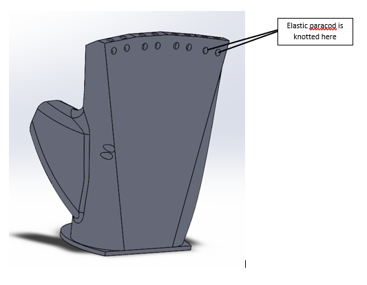
For each finger, there are 3 separated parts which are connected together to the palm using an elastic paracord. The paracord is threaded by the two highlighted holes in the above picture.


To bend the finger from the open position, a force is applied to the other side of the paracord.
b. Palm
Each finger is connected to the palm using the same paracord which connects 3 parts of it together.
The paracord then is knotted using two holes shown above to position the finger to the palm.
The palm is then attached to the forearm using super plastic glue.
c. Forearm

There will be a “servo holder” in which all the servos are screwed into it. Afterwards, the servo holder will be attached to the specific position above.

d. Assembly of the arm

2.4Mechanism
2.4.a 3-lead Muscle/Electromygraphy Sensor
What is electromyography? - Measuring muscle activation via electric potential, referred to as electromyography (EMG), has traditionally been used for medical research and diagnosis of neuromuscular disorders. However, with the advent of ever shrinking yet more powerful microcontrollers and integrated circuit, EMG circuits and sensors have found their way into prosthetics, robotics and other control systems.
Layout of sensor

Set-up

Why is the electrode placement essential? - Position and orientation of the muscle sensor electrodes has a vast effect on the strength of the signal. The electrodes should be placed in the middle of the muscle body and should be aligned with the orientation of the muscle fibers. Placing the sensor in other locations will reduce the strength and quality of the sensor's signal. From our experience, the sensor gives the best performance when attached to our bicep muscle.
2.4.c How it works?
At first, the muscle sensor will be attached to a person's bicep by using three electrodes. After setting up and following our schematics, the Prosthetic Arm is now ready to function. When he/she flexes the bicep muscle, the sensor will take the signal and send it to the microcontroller. According to the program we wrote in Arduino IDE, the signal will then be converted to power through our Math equation to power Four servos to bend five fingers.
·-> Our result: https://www.youtube.com/watch?v=mZ35tk0hR1w&feature=emb_title
2.6 Challenges and Future work
At first, we wanted to design an arm which we can control each finger individually. However, the muscle sensor can only send one signal to the microcontroller - an Arduino. As a result, all five fingers will have to move at the same time. For now, as what we understand, in order to control each finger separately, we will need to attach a sensor to different muscles which control different fingers. So that when a particular muscle is being used, the finger associated with it will be controlled and not other fingers.
Initially, only two servos were used to controlled five fingers. However, both are not strong enough and the servo horns i designed started to slip. Consequently, we had to introduce another two servos to control the fingers since it requires only four servos to control five fingers.
There will be lots to come with our design since for now, the ring finger and the pinky fingers are controlled at the same time. In the near future, a lot of modification will be required!
3. CONCLUSION
Throughout the process of perfecting our project, we have encountered a lot of challenegs which we think of it as an effective way for us to learn. It is a great opportunity to do some kind of hands-on project so that we understand that in order to solve a problem, it requires time, sweat and tears. At the end, even though there are a lot to come with this project, we are happy about it. A project that I dreamed about eventually comes to reality.


Comments